<?xml version="1.0" encoding="utf-8"?><feed xmlns="http://www.w3.org/2005/Atom" ><generator uri="https://jekyllrb.com/" version="3.10.0">Jekyll</generator><link href="https://robosangli.github.io//feed.xml" rel="self" type="application/atom+xml" /><link href="https://robosangli.github.io//" rel="alternate" type="text/html" /><updated>2026-03-12T10:50:35+00:00</updated><id>https://robosangli.github.io//feed.xml</id><title type="html">Ananda Sangli’s Projects</title><subtitle>A website hosting Ananda Sangli&apos;s projects.</subtitle><author><name>Ananda Sangli</name></author><entry><title type="html">NU Localization via Wi-Fi through RSSI/BSSID Pair Training</title><link href="https://robosangli.github.io//eece5554-wifi-based-localization/" rel="alternate" type="text/html" title="NU Localization via Wi-Fi through RSSI/BSSID Pair Training" /><published>2025-12-12T00:00:00+00:00</published><updated>2025-12-12T00:00:00+00:00</updated><id>https://robosangli.github.io//eece5554-wifi-based-localization</id><content type="html" xml:base="https://robosangli.github.io//eece5554-wifi-based-localization/"><![CDATA[<p>Timeline: Fall 2025<br />
Location: Boston, MA, USA<br />
Skills:</p>

<p>For the final project in the Robotics Sensing &amp; Navigation (EECE 5554) course at Northeastern University, I worked with two peers to develop a Wi-Fi localization system using RSSI/BSSID Pair Training.</p>

<p>I worked on the development, implementation, and evaluation of learning-based localization methods to estimate planar position from WiFi signal data. This involved,</p>
<ul>
  <li>Designing regression models that take BSSID-indexed RSSI measurements as inputs and output estimated (x, y) coordinates</li>
  <li>
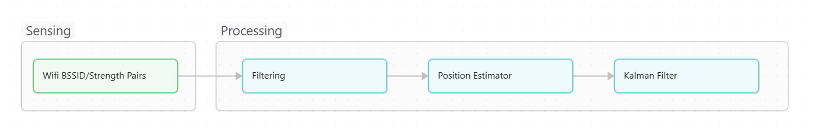
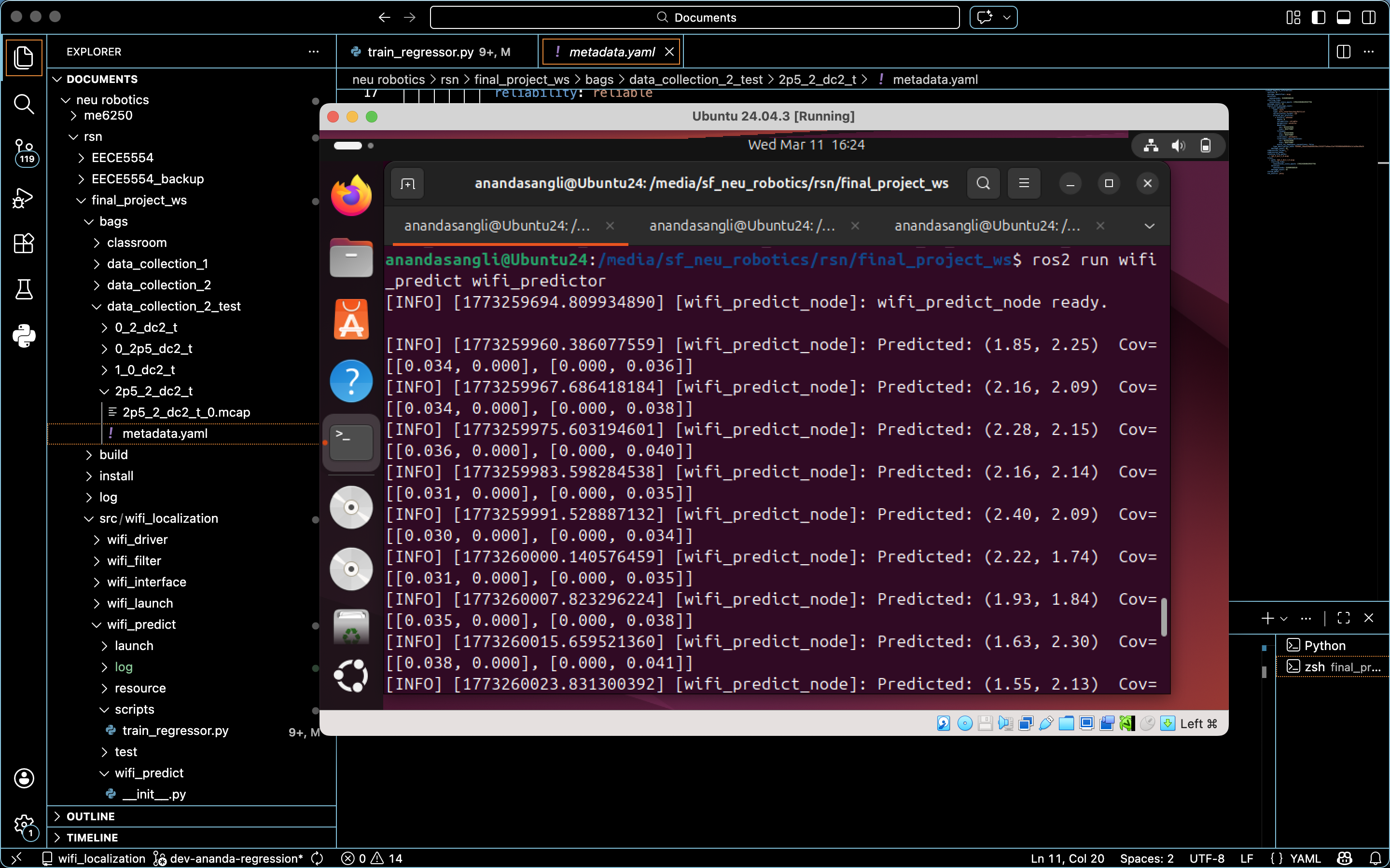
Implementing these models as a ROS2 prediction node that integrates with the system-wide sensing and filtering pipeline</li>
  <li>Performing data analysis and quantitative evaluation to assess localization accuracy and system efficacy</li>
</ul>

<p>My other 2 team members, Jack and Ben, focused on complementary system components like the Sensing and Filtering aspects of the pipeline. This included the ROS2 Wi-Fi driver, custom message definitions, low-pass filtering of raw RSSI measurements, and Kalman filtering for temporal smoothing. My development of the core inference layer of the localization system is wrapped in a ROS2 Python Node with a regression training Python script.</p>

<figure class="align-center">
<img src="/assets/images/wifi-based-loc-system-overview.png" />
<figcaption> System Pipeline Overview </figcaption>
</figure>

<p>I followed a process of analysing the data, experimenting with various models, and producing the necessary results for filtering.</p>

<h3 id="sensing-modality-data-challenges">Sensing Modality Data Challenges:</h3>
<ul>
  <li>High dimensionality &amp; sparsity: Only a subset of all the access points for each Wi-Fi scan</li>
  <li>Measurement noise &amp; temporal variability</li>
  <li>Nonlinear spatial relationships
Despite these challenges, Wi-Fi was chosen for its infrastructure-free and low-cost sensing capabilities.</li>
</ul>

<figure class="align-center">
<img src="/assets/images/wifi-based-loc-data-collection.jpg" />
<figcaption> Data Collection in EXP Highbay </figcaption>
</figure>

<h3 id="data-representation--preprocessing">Data Representation + Preprocessing</h3>
<p>
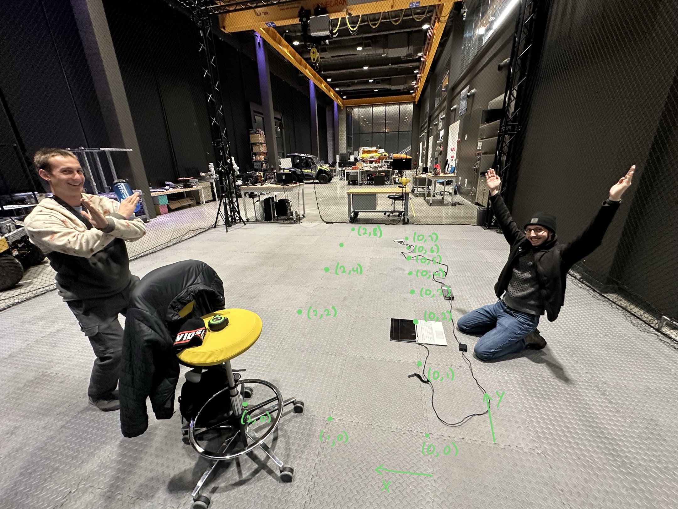
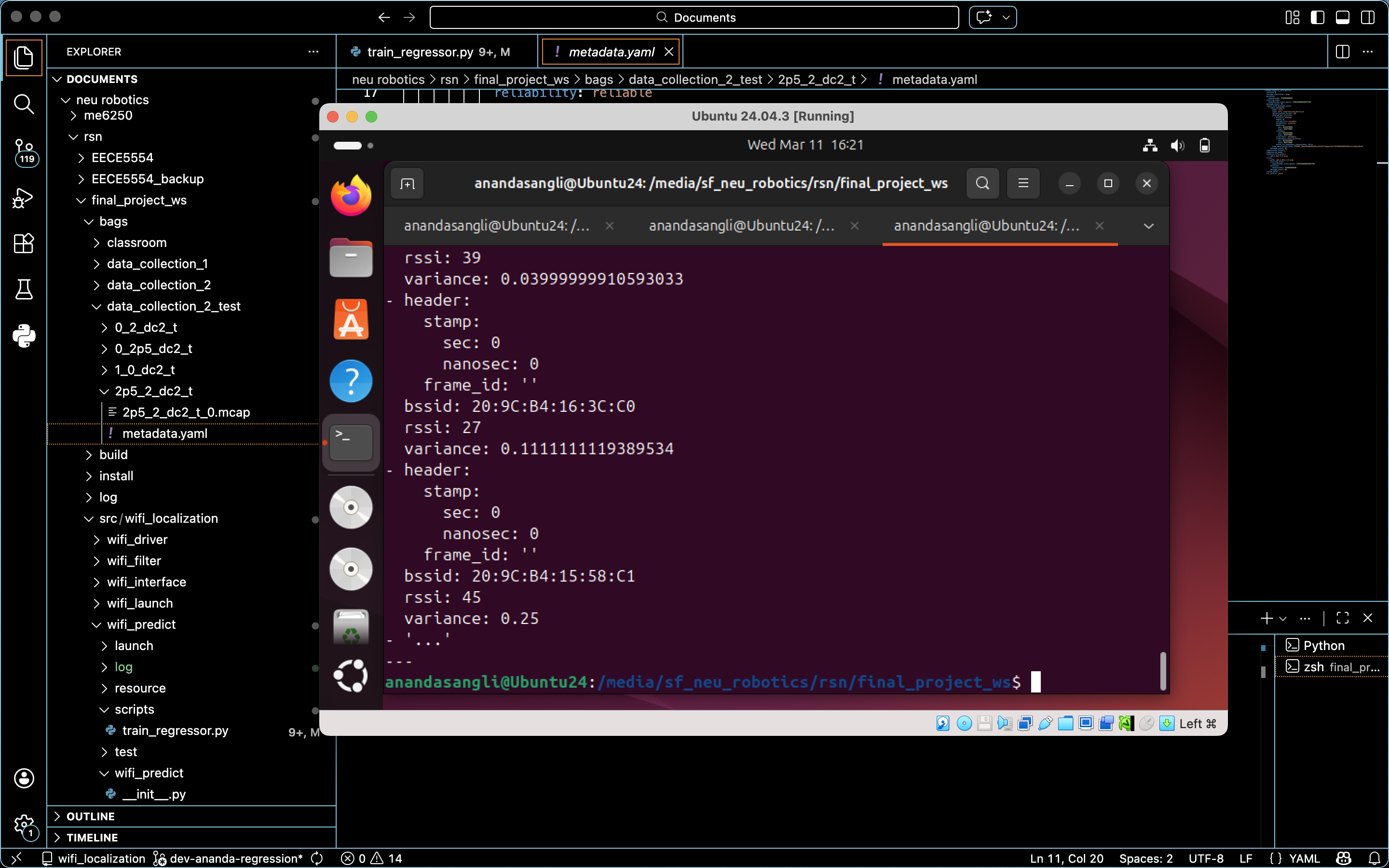
Wi-Fi scans recorded consisted of variable-length access point observations, which are incompatible with standard regression models. To address this, I used a fixed-dimensional representation indexed by BSSID. I used mean imputation to handle the missing RSSI values. As a result, the consistently observed access points were incorporated into the model. 
I also implemented a variance-based feature selection to remove access points with low informational content.</p>

<h3 id="candidate-modeling-approaches">Candidate Modeling Approaches</h3>
<p>I implemented 3 approaches, each with increasing complexity.</p>
<ul>
  <li>Lazy learning or fingerprinting: Evaluated as an initial baseline due to their simplicity but they scaled poorly with dataset size and did not provide reasonable estimates. Downstream probabilistic filtering was probably necessary to address accuracy concerns in the training dataset.</li>
  <li>
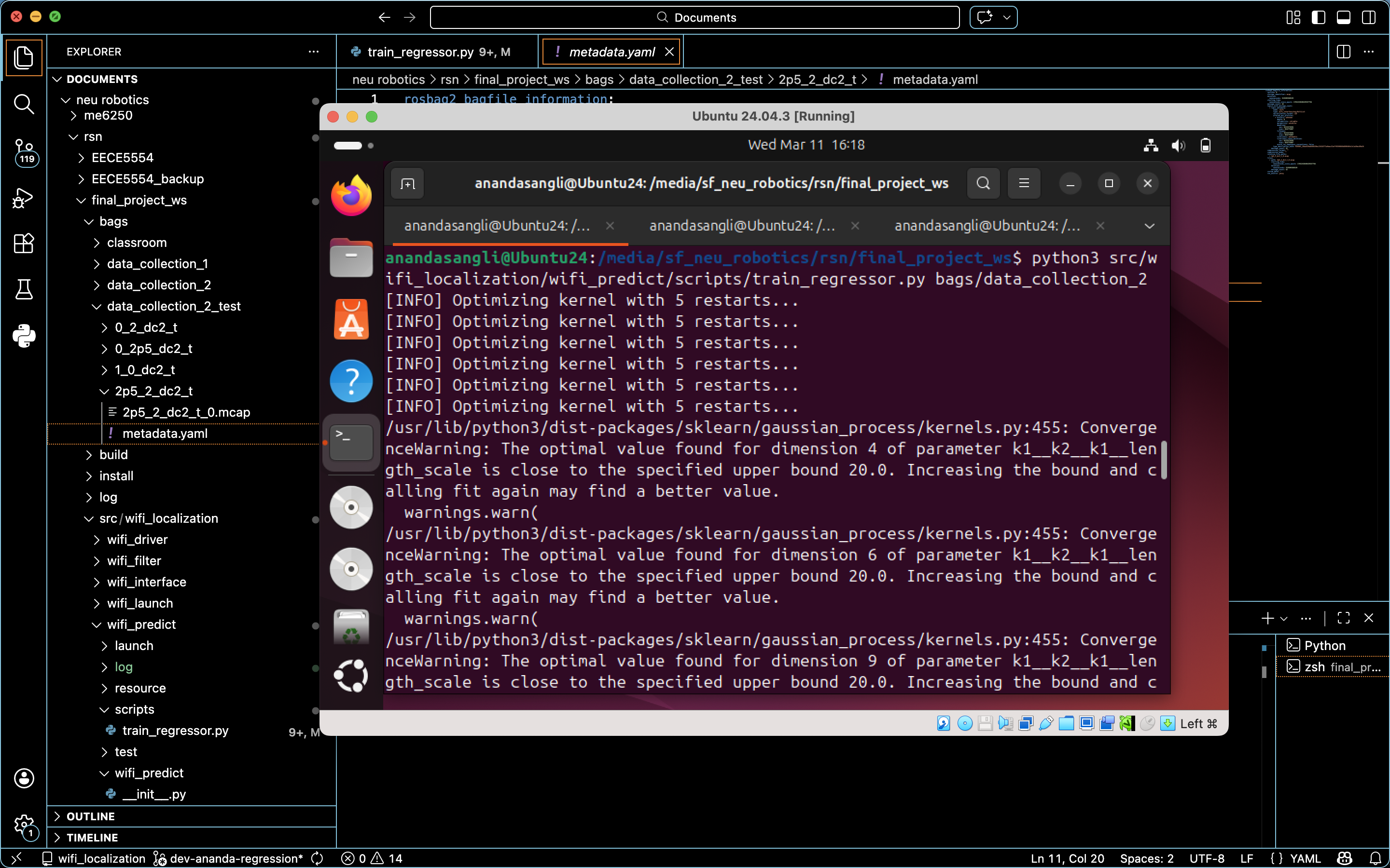
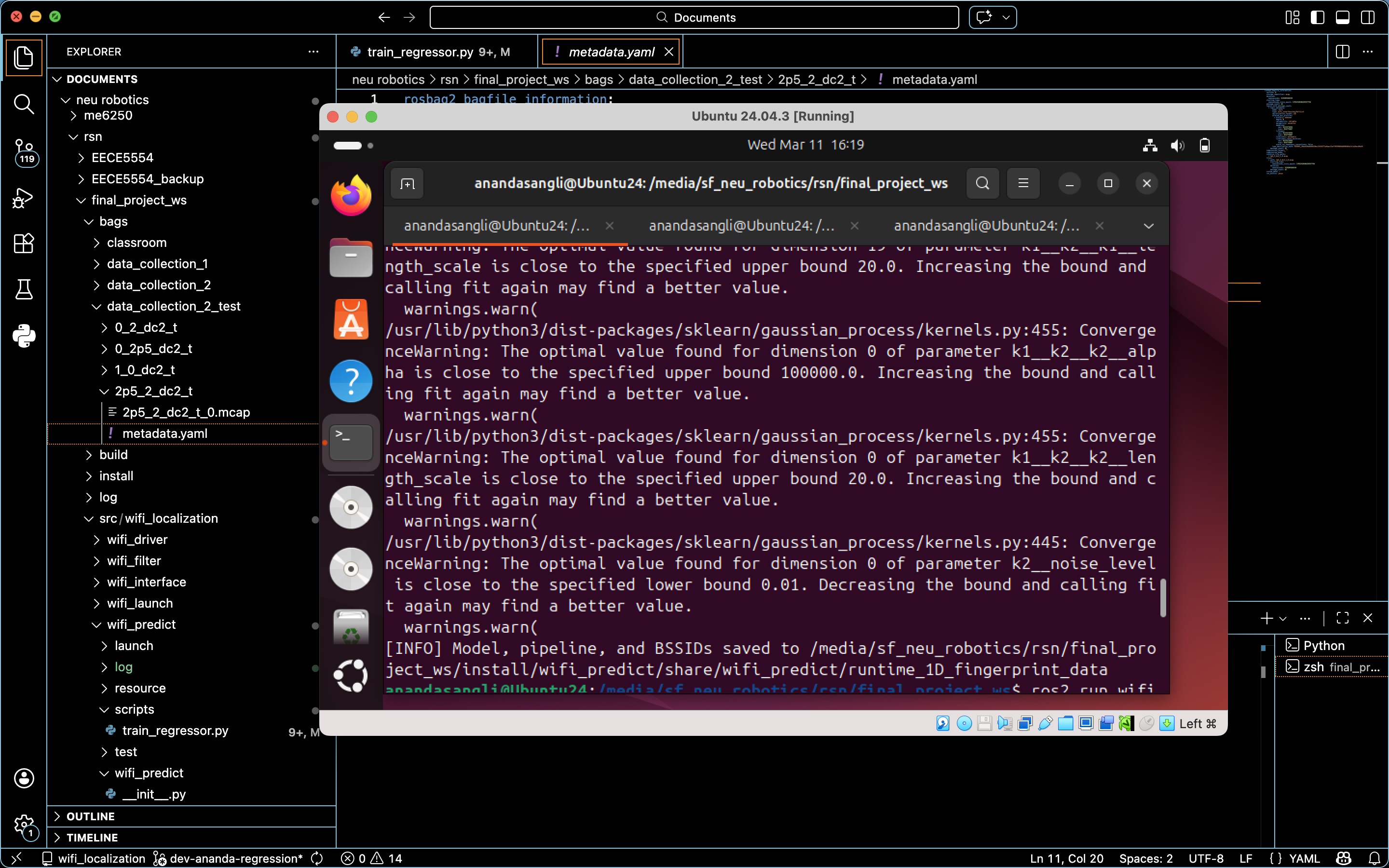
Gaussian Process Regression (GPR): Trained a single multi-output GP and observed its ability to model nonlinear relationships while quantifying predictive uncertainty.</li>
  <li>Multi-output regression formulations using GPR: Two independent GPs, one for each spatial dimension (x, y), which yielded the highest predictive accuracy.</li>
</ul>

<h3 id="results">Results</h3>
<p>Gaussian Process Regression, when combined with structural preprocessing and careful kernel design, was shown to be well-suited for Wi-Fi-based indoor localization. We successfully achieved 2-Dimensional localization with sufficiently accurate position estimates.</p>

<figure class="align-center">
<img src="/assets/images/wifi-based-loc-train-regressor.png" />
<figcaption> Training Regressor </figcaption>
</figure>

<figure class="align-center">
<img src="/assets/images/wifi-based-loc-training-complete.png" />
<figcaption> Training completed </figcaption>
</figure>

<figure class="align-center">
<img src="/assets/images/wifi-based-loc-play-rosbag-for-testing.png" />
<figcaption> Play pre-collected ROSbag (for testing) - Position (2.5,2) </figcaption>
</figure>

<figure class="align-center">
<img src="/assets/images/wifi-based-loc-echo-wifi.png" />
<figcaption> Echo '/wifi' topic to confirm </figcaption>
</figure>

<figure class="align-center">
<img src="/assets/images/wifi-based-loc-wifi-predictor.png" />
<figcaption> Run Wifi Predictor </figcaption>
</figure>

<p>Please note that GenAI was used to debug and help develop this regression, as this project was my first introduction to Machine Learning. I used it as an opportunity to learn as much as I could while keeping up with the rapid development timeline.</p>

<p><a href="https://github.com/robosangli/wifi_localization">Github Code Repo</a>
<a href="https://drive.google.com/file/d/1mV7eSKb1KLgF4JEs_iNp0PSw4UIq2qgF/view?usp=sharing">Report</a>
<a href="https://drive.google.com/file/d/1P3ir1rHqdzVZI9zGP4wqrHtJfiAFUdXk/view?usp=sharing">Presentation Slides</a></p>]]></content><author><name>Ananda Sangli</name></author><summary type="html"><![CDATA[Localization via Wi-Fi through RSSI/BSSID Pair Training - Final Project for EECE 5554 (Northeastern University)]]></summary></entry><entry><title type="html">NU Camera Orbit Trajectory through Co-robot Arm</title><link href="https://robosangli.github.io//me5250-orbit-trajectory/" rel="alternate" type="text/html" title="NU Camera Orbit Trajectory through Co-robot Arm" /><published>2025-12-12T00:00:00+00:00</published><updated>2025-12-12T00:00:00+00:00</updated><id>https://robosangli.github.io//me5250-cobot-camera-orbit-trajectory</id><content type="html" xml:base="https://robosangli.github.io//me5250-orbit-trajectory/"><![CDATA[<p>Timeline: Fall 2025<br />
Location: Boston, MA, USA<br />
Skills: Python, Forward Kinematics (DH Parameters), Inverse Kinematics (Newton-Damped Least-Squares), Trajectory Planning</p>

<!-- <figure class="align-center">
<img src= "/assets/images/tri-brake-ecu-to-actuator-wire.png">
<figcaption> A wire I fabricated to connect the brake ECU to the actuator, thereby setting up the vehicle's brake-by-wire technology</figcaption>
</figure> -->

<p>Inspired by industrial inspections performed by co-robot arms equipped with a visual sensor that captures data from multiple angles of the object, I created an animation of the end-effector’s camera orbit trajectory circling a target point. This fulfills the inspection criteria by being aimed at the object’s center while maintaining consistent lighting, stable viewpoint geometry, and uniform feature coverage. This was for the second project in my Robot Mechanics and Control (ME 5250) course at Northeastern University.</p>

<p>To set up the Kinematics, I used the official UR10e DH Parameters. I then implemented Forward Kinematics using DH Transform matrices. Using the equation, I wrote code to compute the end-effector given the joint angles.
I also implemented a Newton-Raphson-based inverse kinematics solver. The code uses the Damped Least Squares method to avoid singularities, and the desired end-effector pose is used to compute the required joint angles.
While specifying the trajectory, for an initial resolution of 1mm, 1600 waypoints were needed. This was reduced to 400 waypoints to reduce animation runtime.</p>

<video controls="" width="600">
  <source src="/assets/videos/me5250-project2-animation.mp4" type="video/mp4" />
 6DOF UR10e animation for Camera Orbit Trajectory
</video>

<p>The animation produced is an attempt at this trajectory. While the trajectory demonstrates smooth 3D motion and full 6-DOF motion with no singularities for the most part, it is difficult to identify the continuous orientation control. This is apparent when observing the RGB end-effector frame. Only a few irregular motions are observed due to singularities.</p>

<p>The code I used is shared on the <a href="https://github.com/robosangli/co-robot-camera-orbit-trajectory">Github Code Repo</a>.</p>

<p>In the future, I hope to improve 3D motion smoothness by implementing more robust FK and IK solvers. It would also be interesting to explore collision avoidance and extend this study to dynamics and control.</p>

<p><a href="https://drive.google.com/file/d/1kW-ZbZ1q9C_i6x_wlm8V1jHffvTgfrrN/view?usp=drive_link">Project Report</a></p>]]></content><author><name>Ananda Sangli</name></author><summary type="html"><![CDATA[The animation video for the Camera Orbit Trajectory through a 6-DOF Co-robot Arm for ME 5250 (Northeastern University)]]></summary></entry><entry><title type="html">NU GPS-IMU Sensor Fusion for Vehicle Position Estimation</title><link href="https://robosangli.github.io//eece5554-car-navigation/" rel="alternate" type="text/html" title="NU GPS-IMU Sensor Fusion for Vehicle Position Estimation" /><published>2025-12-03T00:00:00+00:00</published><updated>2025-12-03T00:00:00+00:00</updated><id>https://robosangli.github.io//eece5554-car-navigation</id><content type="html" xml:base="https://robosangli.github.io//eece5554-car-navigation/"><![CDATA[<p>Timeline: Fall 2025<br />
Location: Boston, MA, USA<br />
Skills:</p>

<p>As part of the Robotics Sensing and Navigation (EECE 5554) course curriculum at Northeastern University, I worked with 2 peers on GPS-IMU sensor fusion to determine a moving car’s path.</p>

<p>We first verified the working of each individual driver, gps_driver, and vn_driver to ensure the proper functioning of each individual component (GPS &amp; IMU). Then we verified the fusion of the data streams from these two sensors.</p>

<figure class="align-center">
<img src="/assets/images/car-nav-testing-setup.png" />
<figcaption> Car Setup Testing </figcaption>
</figure>

<figure class="align-center">
<img src="/assets/images/car-nav-imu-placement-on-dash.png" />
<figcaption> IMU Dash Setup </figcaption>
</figure>

<p>Then we collected data in 4 environments: stationary, stationary with the engine idle, a circular path, and driving in Boston through traffic.</p>

<video controls="" width="600">
  <source src="/assets/videos/car-nav-circular-path.mp4" type="video/mp4" />
 Circular Path Data Collection
</video>

<video controls="" width="600">
  <source src="/assets/videos/car-nav-boston-traffic.mp4" type="video/mp4" />
 Boston Traffc Data Collection (snippet)
</video>

<p>We calculated the calibration from magnetometer data using least-squares. We then plotted the accelerometer and gyro data, along with their time integrals. With this data from the VN and GPS, we plotted the vehicle’s path. We ended our exploration with a brief discussion on the sources of error in this path/position estimation.</p>

<p>For more details please take a look at the <a href="https://github.com/robosangli/nuance_navigation">Github</a> and the <a href="https://drive.google.com/file/d/1edk2zzMs9VqS_tcLH5IIqBwc4JlY6u4l/view?usp=sharing">Report</a></p>]]></content><author><name>Ananda Sangli</name></author><summary type="html"><![CDATA[GPS-IMU Sensor Fusion for Vehicle Position Estimation for EECE 5554 (Northeastern University)]]></summary></entry><entry><title type="html">NU Double Parallelogram RCM Mechanism</title><link href="https://robosangli.github.io//me5250-rcm-mechanism/" rel="alternate" type="text/html" title="NU Double Parallelogram RCM Mechanism" /><published>2025-11-07T00:00:00+00:00</published><updated>2025-11-07T00:00:00+00:00</updated><id>https://robosangli.github.io//me5250-double-parallelogram-rcm-cad</id><content type="html" xml:base="https://robosangli.github.io//me5250-rcm-mechanism/"><![CDATA[<p>Timeline: Fall 2025<br />
Location: Boston, MA, USA<br />
Skills: 3D CAD (Onshape)</p>

<p>Inspired by the parallelogram mechanism in robots like the Da Vinci system in Minimally Invasive Surgery, I explored the design and analysis of a double-parallelogram remote center of motion mechanism. This was for my first project in my Robot Mechanics and Control (ME 5250) course at Northeastern University.</p>

<p>To further understand this mechanism’s ability to rotate its end-effector around a fixed point without the presence of a physical revolute joint, I performed a survey of the existing literature. I first looked at 1-DOF RCM mechanisms formed by combining two parallelogram linkages, as seen below</p>

<figure class="align-center">
<img src="/assets/images/me5250-1dof.png" />
<figcaption> 1-DOF Double parallelogram RCM </figcaption>
</figure>

<p>I then moved on to 2-DOF RCM mechanisms formed by the serial connection of two parallelograms.</p>

<figure class="align-center">
<img src="/assets/images/me5250-2dof+mobility.jpg" />
<figcaption> 2-DOF Double parallelogram RCM + Mobility Analysis </figcaption>
</figure>

<p>I performed a mobility analysis using Grubler’s formula to demonstrate 2 DOF while maintaining a total joint count of 9. Intuitively, this made sense as the translation/insertion motions along the tool axis (end-effector).</p>

<p>I then used a simplified kinematic model of the mechanism to compute the Jacobian matrix of the linkage and identify the existing singularities (as shown in the report).</p>

<figure class="align-center">
<img src="/assets/images/me5250-simplified-kinematics-model.png" />
<figcaption> Simplified Kinematics Model </figcaption>
</figure>

<p>This project introduced me to the complex mechanics of remote-center-of-motion mechanisms, particularly double-parallelogram mechanisms. For more details, please refer to the <a href="https://drive.google.com/file/d/10gav7T_xcN6B1vySFROKQxyaBcYVikXJ/view?usp=sharing">Project Report</a>.</p>]]></content><author><name>Ananda Sangli</name></author><summary type="html"><![CDATA[The design & analysis of a double parallelogram RCM mechanism for ME 5250 (Northeastern University)]]></summary></entry><entry><title type="html">NU Robot Wrist Mechanism animation</title><link href="https://robosangli.github.io//me5250-robot-wrist/" rel="alternate" type="text/html" title="NU Robot Wrist Mechanism animation" /><published>2025-09-22T00:00:00+00:00</published><updated>2025-09-22T00:00:00+00:00</updated><id>https://robosangli.github.io//me5250-robot-wrist-mechanism-cad</id><content type="html" xml:base="https://robosangli.github.io//me5250-robot-wrist/"><![CDATA[<p>Timeline: Fall 2025<br />
Location: Boston, MA, USA<br />
Skills: 3D CAD (Onshape)</p>

<p>For the Robot Mechanics and Control (ME 5250) course at Northeastern University, I 3D modeled a 3-DOF parallel wrist mechanism based on the provided design. My model verified grounded/parallel actuation of all three DOFs.</p>

<p>Here is the video!</p>

<video controls="" width="600">
  <source src="/assets/videos/me-5250-robot-wrist-mechanism-animation.mp4" type="video/mp4" />
  Robot Wrist Mechanism CAD modeled by me with 3 R-joints, 5 U-joints, 1 S-joint, 1-P joint, and 2 C-joints
</video>

<p>I built this model to better understand the original parallel wrist mechanism shown below.</p>

<figure class="align-center">
<img src="/assets/images/me5250-robot-wrist-original-mechanism.png" />
<figcaption> Original Mechanism </figcaption>
</figure>

<p>With the annotations (links and joints), I performed a mobility analysis of the mechanism using Grubler’s equation to verify that it has 3 DOF.</p>

<figure class="align-center">
<img src="/assets/images/me5250-robot-wrist-annotated-mechanism.png" />
<figcaption> Annotated Mechanism </figcaption>
</figure>

<p>I also created drawings of the model to better showcase the 3D modeling. For more details, please take a look at the <a href="https://drive.google.com/file/d/1XqRkYsD7mi-k4qvhuJm0crDoMB9CKwip/view?usp=sharing">Project Report</a>.</p>]]></content><author><name>Ananda Sangli</name></author><summary type="html"><![CDATA[The animation video for a robot wrist mechanism for ME 5250 (Northeastern University)]]></summary></entry><entry><title type="html">Hullbot Underwater Robot Operator</title><link href="https://robosangli.github.io//hullbot-operator/" rel="alternate" type="text/html" title="Hullbot Underwater Robot Operator" /><published>2025-06-02T00:00:00+00:00</published><updated>2025-06-02T00:00:00+00:00</updated><id>https://robosangli.github.io//hullbot-operator</id><content type="html" xml:base="https://robosangli.github.io//hullbot-operator/"><![CDATA[<p>Timeline: February 2025 - May 2025<br />
Location: San Francisco, CA, USA<br />
Skills: Operations</p>

<p>Hullbot is a robotics startup based in Sydney, Australia with a mission of decarbonizing the global maritime industry by addressing three areas: carbon emissions, microplastics &amp; toxic paints, biosecurity.</p>

<p>I support biweekly cleans of the SF Bay Ferries to reduce the biofouling on the hulls, thereby saving fuel and reducing emissions.</p>

<p>The ferry structure consists of 2 keels and for each clean two operations work on opposite sides of the hull (port &amp; starboard) effectively.</p>

<figure class="align-center">
<img src="/assets/images/hullbot-ferry-view.png" />
<figcaption>This is the view from the bow of the ferry. Operations originating from here allow cleans until the midship due to the length of the tether</figcaption>
</figure>

<p>To clean the sections between the midship and the stern (including the fins) the robot is operated at a different location.</p>

<p>The setup usually involves the hullbot robot, the tether spool, an underwater pressure tester, and a computer that relays the camera &amp; positioning data to the operator. The robots have depth, cruise, and hull-hold control capabilities which simplify the teleoperation process. This is particularly important in challenging conditions with vortices and reduced depth visibility</p>

<figure class="align-center">
<img src="/assets/images/hullbot-operation-setup.png" />
<figcaption>Operational Setup</figcaption>
</figure>

<figure class="align-center">
<img src="/assets/images/hullbot-operation-team.png" />
<figcaption>Working with my co-operator as the "port-side" team for one of the cleans!</figcaption>
</figure>

<p>​<a href="https://www.hullbot.com/">Hullbot</a></p>]]></content><author><name>Ananda Sangli</name></author><summary type="html"><![CDATA[Operate underwater robots to reduce marine biofouling on ferries, thereby improving their fuel efficiency.]]></summary></entry><entry><title type="html">TRI System Integration Engineer</title><link href="https://robosangli.github.io//tri-engineer/" rel="alternate" type="text/html" title="TRI System Integration Engineer" /><published>2025-06-01T00:00:00+00:00</published><updated>2025-06-01T00:00:00+00:00</updated><id>https://robosangli.github.io//tri-engineer</id><content type="html" xml:base="https://robosangli.github.io//tri-engineer/"><![CDATA[<p>Timeline: September 2024 - May 2025<br />
Location: Los Altos, CA, USA<br />
Skills: SOLIDWORKS, Laser Cutting, Perception &amp; Localization</p>

<p>I continued to assist in developing a new off-road battery electric vehicle with my previous responsibilities.</p>

<h3 id="vehicle-compute-stack">Vehicle Compute Stack</h3>
<figure class="align-center">
<img src="/assets/images/tri-delrin-tablesaw-compute-stack.PNG" />
<figcaption> I used the in-house tablesaw to cut 1/4" Delrin plates to fabricate the first iteration of the vehicle's compute stack to house onboard computers</figcaption>
</figure>
<p>I utilized Solidworks guides to create 2D Drawings and image trace sketches. I also utilized the Solidworks Hole Wizard to automatically create screw clearances, adjusting for real-world inconsistencies from CAD data.</p>

<p>I also selected appropriate high-strength (class 10.9 &amp; 8) zinc-plated steel fasteners (to prevent galling) like flange nuts &amp; 100° countersink screws to accommodate for steel-aluminum interactions and nut-to-bolt tensile strengths.</p>

<p>As seen above, I fabricated a prototype shelf utilizing a table saw and laser cutter for 1/4” Delrin plates and stainless steel standoffs between these plates and shelves for easy modular installation. Since the plates were larger than the laser cutter bed, the bottom holes were manually drilled (to avoid rotation-recut alignment issues with the laser cutter).</p>

<p>I also communicated with the sheet-metal fabricator for Aluminum counterparts to replace the Delrin in the long-term with deep laser engraving post the anodizing finish.</p>

<h3 id="wheel-speed-sensor-integration">Wheel-speed sensor integration</h3>
<p>I studied existing documentation &amp; in-vehicle wiring for 4 individual in-hub wheel-speed sensors. As a result, I identified the correct brake ECU pins to integrate the sensors &amp; transfer output to the low-level computer.</p>

<p>I fabricated long-run sensor wires and integrated them into brake ECU to identify the correct CAN channel by monitoring bus traffic through a CAN-USB interface and monitoring software (Vector CANalyzer).</p>

<p>I am currently integrating these wheel-speed sensors to facilitate high-level software and autonomous control of the vehicle.</p>

<h3 id="high-voltage-battery-build">High Voltage Battery Build</h3>
<p>I supported with the build of a 35.7kWh 400V Li-ion battery pack comprising of 3 battery strings in parallel and 7 cells in series in each string.</p>

<p>I started by sourcing all the necessary parts. This introduced me to HV contactors, current transducer sensors, battery management systems, cooling (heat exchanger, reserve tank, pumps) and the mechanical components needed like aluminum bridges, and copper busbars. I worked on the in-house CNC machining of certain parts like L-channel brackets below, and created the enclosure welding diagram (comprising of steel tubing and threaded+unthreaded sleeves).</p>

<figure class="align-center">
<img src="/assets/images/tri-battery-channel-cnc-machining.png" />
<figcaption> It was my first time operating the CNC Machine with no assistance to drill precise holes into L-channels that keep the side panels for each battery string in place</figcaption>
</figure>

<p>I also assisted in the build of a 3D printed box to house 9 contactors, 3 current transducer sensors, and 3 automobile resistors. This will help in safely controlling the battery.</p>

<figure class="align-center">
<img src="/assets/images/tri-contactor-box-heat-set-insertion.png" />
<figcaption> It was exciting learning about the robustness of threaded heat-set inserts into 3D printed components for improved design robustness</figcaption>
</figure>

<h3 id="perception--localization">Perception &amp; Localization</h3>
<p>I was introduced to the planar calibration difficulties with vehicle visual-inertial sensors and AprilTag boards for initial calibrations for computer vision systems.</p>

<p>I was also introduced to the framework used to label lane boundaries dealing with muliple frames (camera frame, imu frame, body frame, road frame, ground frame) extrinsic &amp; intrinsic parameters, and tangential &amp; radial distortions.</p>

<p>I set up software on my local system in terms of vision-based model predictive control, SAM2 (Segment Anything Model 2) for object segmentation, MATLAB, AWS data buckets (for rosbag data), and lane-boundary labeling scripts.</p>

<p>This allowed me to study GPS RTK (real-time kinematics) technology to better understand the onboard INS (inertial navigational system) and the ground truth calculations for vehicles.</p>

<h3 id="other-tasks--support">Other tasks + Support</h3>
<p>I successfully integrated a human-machine interface keypad and buttons after testing on dSPACE layouts, thereby establishing analog detection emergency-stop capabilities and BMS (battery management system) signals. The resulting documentation will be utilized as vehicle operations for all future users.</p>

<p>I supported in the development &amp; preparation for the vehicle’s first driving tests in terms of wiring refabrications, rerouting, and other electrical clean-ups to prevent communication errors.</p>

<p>I also supported the team in loading the vehicle’s battery (pack + enclosure) through a 2 post-lift. We made adjustments of the rear shock absorber springs and re-aligned the wheels to compensate for the battery’s weight.</p>

<p>I supported the team on vehicle drive tests incorporating torque limits (400Nm &amp; 500Nm) before adding water for battery cooling. We discovered issues during this mechanical shakedown.</p>

<p>I also reviewed Simulink vehicle interface software merge requests made by the team for vehicle software integration across various low-level components like the BMS (Battery Management System), HMI (Human-Machine Interface) devices, and inverter-motor-gearbox modules.</p>

<p>​<a href="https://www.tri.global/our-work/human-interactive-driving">Toyota Research Institute: Human Interactive Driving</a></p>]]></content><author><name>Ananda Sangli</name></author><summary type="html"><![CDATA[Designed a stack for on-board computers, integrating wheel-speed sensors, and exploring the perception & localization framework.]]></summary></entry><entry><title type="html">TRI Intern</title><link href="https://robosangli.github.io//tri-intern/" rel="alternate" type="text/html" title="TRI Intern" /><published>2024-08-30T00:00:00+00:00</published><updated>2024-08-30T00:00:00+00:00</updated><id>https://robosangli.github.io//tri-intern</id><content type="html" xml:base="https://robosangli.github.io//tri-intern/"><![CDATA[<p>Timeline: December 2023 - August 2024<br />
Location: Los Altos, CA, USA<br />
Skills: MATLAB, Simulink, ROS2, Python, dSPACE</p>

<p>I was an intern on the Platform Research team in Human Interactive Driving at Toyota Research Institute. I integrated mechatronic components to build a new off-road &amp; high-torque battery electric vehicle.</p>

<h3 id="brake-by-wire">Brake-by-wire</h3>
<figure class="align-center">
<img src="/assets/images/tri-brake-ecu-to-actuator-wire.png" />
<figcaption> A wire I fabricated to connect the brake ECU to the actuator, thereby setting up the vehicle's brake-by-wire technology</figcaption>
</figure>
<p>I implemented a reliable brake-by-wire architecture with 4 individually controllable caliper pressures, thereby providing higher autonomous control capabilities.</p>

<p>I integrated the brake pedal position sensor to require lesser driver pedal application pressure than traditional brake systems, thereby reducing stopping distances.</p>

<p>I also established communication between the main computer, brake ECU (Engine Control Unit), pedal sensor, and stroke sensor via Simulink &amp; CAN (Controller Area Network) bus communication to allow for shared control capabilities between the brake pedal &amp; an autonomous braking system.</p>

<p>Finally, I utilized the dSPACE ControlDesk experiment software to verify the brake-by-wire software implementation amongst the internal actuators &amp; solenoids, brake ECU firmware, and the onboard Simulink computer. This was done to ensure optimum conversion of lower-level ECU values to more interpretable values for the vehicle’s shared control.</p>

<h3 id="load-cell-handbrake">Load-cell handbrake</h3>
<p>I deeveloped a ROS2 (Robot Operating System 2) Python package to interface a pressure-sensitive load-cell USB handbrake onto a Linux computer for the vehicle. This removed the need for a traditional cable-based mechanical handbrake.</p>

<p>My package architecture utilizes publisher/subscriber nodes &amp; multithreading with a thread-safe queue. The implementation will allow drivers to drift by locking the vehicle’s rear wheels.</p>

<h3 id="other-explorations">Other explorations</h3>
<p>I started the development &amp; integration of an HMI (Human-Machine Interface) keypad and digital dash display to provide drivers with vital component health metrics</p>

<p>I also utilized Solidworks CAD to design an improved computer shelf system that would allowing for easier access of the vehicle’s computers (remove all at once and debug outside the vehicle). This new design significantly improves on previous vehicles in terms of wiring management and will reduce communication errors.</p>

<p>Additionally, I explored a 48V DC Brushless motor (with an integrated controller) to independently steer a wheel for future battery electric vehicles through a university collaboration. I supported the system design through a custom Simulink state machine implementing NMT (Network Management) Protocol to control the CANOpen motor’s state &amp; identify error codes through PDOs (Process Data Objects) &amp; SDOs (Service Data Objects).</p>

<p>​<a href="https://www.tri.global/our-work/human-interactive-driving">Toyota Research Institute: Human Interactive Driving</a></p>]]></content><author><name>Ananda Sangli</name></author><summary type="html"><![CDATA[Integrated & implemented the brake-by-wire system, and developed a ROS2 Python package for a load-cell handbrake]]></summary></entry><entry><title type="html">Impossible Objects Application Engineer</title><link href="https://robosangli.github.io//io-engineer/" rel="alternate" type="text/html" title="Impossible Objects Application Engineer" /><published>2024-04-26T00:00:00+00:00</published><updated>2024-04-26T00:00:00+00:00</updated><id>https://robosangli.github.io//io-engineer</id><content type="html" xml:base="https://robosangli.github.io//io-engineer/"><![CDATA[<p>Impossible Objects leverages advanced additive manufacturing techniques to revolutionize the wave soldering process for electronic circuit boards with Carbon Fiber composite boards. 
I designed efficient solder pallets utilizing Fusion 360 (3D CAD) to be made using the CBAM (Composite Based Additive Manufacturing) printers created by Impossible Objects.</p>

<p>One of my designs is shared below.</p>

<figure class="align-center">
<img src="/assets/images/io-isometric-1.png" />
<figcaption> Isometric View 1 </figcaption>
</figure>

<figure class="align-center">
<img src="/assets/images/io-top.png" />
<figcaption> Top View </figcaption>
</figure>

<figure class="align-center">
<img src="/assets/images/io-bottom.png" />
<figcaption> Bottom View </figcaption>
</figure>

<figure class="align-center">
<img src="/assets/images/io-isometric-2.png" />
<figcaption> Isometric View 2 </figcaption>
</figure>]]></content><author><name>Ananda Sangli</name></author><summary type="html"><![CDATA[Designed PCB pallets to be used in the wave-soldering process]]></summary></entry><entry><title type="html">UIUC Bridge Building Robot</title><link href="https://robosangli.github.io//uiuc-bridge-robot/" rel="alternate" type="text/html" title="UIUC Bridge Building Robot" /><published>2023-05-12T00:00:00+00:00</published><updated>2023-05-12T00:00:00+00:00</updated><id>https://robosangli.github.io//bridge-robot</id><content type="html" xml:base="https://robosangli.github.io//uiuc-bridge-robot/"><![CDATA[<figure class="align-center">
<img src="/assets/images/bridge-robot-final-demo.png" />
<figcaption>Final demo of a 9-layers bridge spanning 28.3 cm in length</figcaption>
</figure>

<p>Timeline: January 2023 - May 2023<br />
Location: University of Illinois at Urbana-Champaign, USA</p>

<p>At the University of Illinois at Urbana-Champaign, my partner and I worked on a UR3 Robot with ROS (Robot Operating System), OpenCV (Computer Vision), and Forward &amp; Inverse Kinematics. Two leaning towers of lire are used to build a bridge. My partner and I placed 3rd overall for building the second tallest bridge (9 layers) with the largest bridge span (28.3 cm). Use the link above to view the image of the final demo.</p>

<p>For more details please access the final project and code using the links below.</p>

<p><a href="https://drive.google.com/file/d/1k0yKHwTPWuxY5g6oSlha2fvscagXPQv2/view?usp=sharing">Project Report</a><br />
<a href="https://github.com/robosangli/LeaningBridgeOfLire">Git Code</a></p>]]></content><author><name>Ananda Sangli</name></author><summary type="html"><![CDATA[Used a collaborative robot arm to build a bridge from small colored wooden blocks]]></summary></entry></feed>